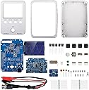
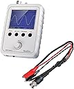
⚡ DIY Your Signal Mastery with Kuman’s Sleek Oscilloscope Shell!
The Kuman JYE DSO Shell Oscilloscope DIY Kit is a compact, 12-bit resolution oscilloscope featuring a 2.4-inch color TFT LCD and an ultra-wide sensitivity range from 5mV/div to 20V/div. Designed with a modular analog board and a full protective enclosure, it offers enhanced signal clarity and easy customization. Its rotary encoder streamlines parameter adjustments, making it ideal for professionals and hobbyists seeking precise, portable electrical testing tools.
| ASIN | B01MY7HAFG |
| Antenna Location | Radio, Remote Control Vehicle |
| Battery Weight | 100 Grams |
| Battery weight | 100 Grams |
| Best Sellers Rank | 151,284 in Business, Industry & Science ( See Top 100 in Business, Industry & Science ) 148 in Lab Oscilloscopes |
| Brand | kuman |
| Brand Name | kuman |
| Customer Reviews | 4.1 out of 5 stars 201 Reviews |
| Item Weight | 100 Grams |
| Manufacturer | Nooelec Inc. |
| Model Number | 15001K-UK |
| Recommended uses for product | Radio, Remote Control Vehicle |
| Reusability | Single Use |
| Unit Count | 1 count |
| Unit count | 1 count |
| Voltage | 10 Volts, 9 Volts |
Z**Y
Great scope for learning.
Great little project to build. This is my first ever scope and got it purely to educate myself. The build went fine but have to warn you that the components are very small and need very good eyesight or a magnifying glass. Soldering skills need to be good to very good. I had trouble reading the resistor values so had to use a multi-meter. Once built, I double checked my solder joints. Then proceeded to the test voltage and calibration. Everything was fine. I run a few sample frequencies into it using Wavelab on my P.C. and the results were spot on. Overall, it's a great bit of kit for the price, it seems very accurate. Take your time when building the kit and double check everything. Great for a beginner scope or those wishing to learn. Great for testing and calibrating audio circuits etc. I don't think it's a project for newbies to electronics or soldering, you must have quite a bit of experience. The instruction manual could have been better as there are functions that are not mentioned by holding down certain keys. Very happy with it.
A**R
Excellent product - pity it is not the latest model
Very pleased with this product. All parts present. The resistors are very small (1/8W) and it helped to have a desk magnifier and a meter to verify the resistor colour codes. All went together with no issues, although the intructions could be a bit clearer when covering which side of the board the test connector needs to be soldered to (looking closely at other pictures helped to identify). Pity this is NOT the latest model (see the manufacturer's website - does not have the voltage regulators on the analogue section). When I buy new I expect to have the latest - oh well... Some screws are very short so very easy to strip the plastic thread if even only slightly overtightened, but with care, most have held.
D**B
DSO150 - latest model, well designed; good engineering for the price point; I can't fault it.
This is the greatly improved version, no more is there any appreciable digitisation noise on the display and the input circuitry has been vastly improved as the previous versions used to suffer from overshoot and poor bandwidth, but this one is now more than adequate. For (I paid) £20 it is about as good as it gets and can be used for nearly all applications making it an ideal product, by-the-way the input range has been extended on this model too, along with a broad range of improvements. So altogether and in-terms of value for money I can't fault it. For me it's a desk top alternative to my full-size digital scope which I can use quickly to check a circuits operation rather than switching on my full size scope (I tend to the larger one in a different position). You shouldn't be disappointed for the price. It's well engineered but read and follow the instructions as you build it as sequencing of assembly is quite important. Some of the resistors are way out but where they are in the circuits does not matter for example 2x15R turned out to be 2x20R so you have to use some logic during the assembly and perhaps start with values that you are sure of. I don't usually tick boxes as I finish assembly, but I did on this scope as component sizes are small.
T**E
Hard kit to solder if you are new to soldering but worth every penny
Requires a modicum of soldering skill but the steps to put together are easy, Putting labels or examples of the codes on the capacitors would make it easier I had to get 3 of the 4 ceramics in then the one left had to be the right one. Put together it works, Please note you need a 9v power supply for the device to work, it would have been nicer to support a 9v battery as well to make it more portable.
R**T
That you should be made to honor picture
The picture you're showing is the wrong item and misleading to all to see,the real item is only£23.99 part no rzs3599768337342ee has correct picture also for sale on your site,thanks for waiting my time and money!!!!!!!!
J**H
This is an amazing little scope.
Now dont get me wrong - this isnt going to rival an ANTEK but it still gets used regularly on my bench. Its great for PWM and audio sources as well as signal tracing. Its pocket sized and will fit easily into the smallest of toolkits. Its not in any way difficult to build and used good quality components. it took a couple of hours to build and install into the case. This is a really cracking little scope. It looks really professional, and its well built (by me). Im very glad i decided to buy this and highly recommend it to others.
S**R
Good value.
Assembled very easily and worked first time. Only criticism is that I cannot persuade the screen to align itself properly with the hole in the case. In operation it takes a little getting used to after operating a convention CRO for so many years, but it does the job nevertheless. I just wish that the case were a little bigger so that there would be room for a rechargeable battery inside.
D**H
Fun Project
The kit was easy to assemble and it worked first time . It's function as an oscilloscope is fairly basic as expected. It would be helpful if the supplied probe had pointed probes as opposed to the supplied alligator clips. Overall fun to build. One point The inline pins must be soldered vertically in the board as the second board has to align with it when plugged in.
E**N
Parfait, pratique, fonctionnel et très bien expliqué
Le montage s'est très bien déroulé. Il faut tout de même avoir un bon faire à souder avec une panne assez fine, en plus de cela ayez un ohmmètre et une pompe à dé-souder sous la main. Pensez également à avoir une alimentation 9V en Jack 5.5 mm Attention, faites correctement la calibration. Finalement si vous suivez étapes par étapes le montage, le tout se fait très bien en un peu moins de 2 heures. Vous pouvez voir ma vidéo qui montre l'oscilloscope en action.
C**O
Coole sache
Ich 15jahre alt und habe es ohne hilfe geschaft zum zusamenbauen. Ein kleiner nachteil die anleitung ist englisch . Aber eine coole sache Lg Christoph
M**O
Consigli utilissimi per il montaggio oscilloscopio DSO 150
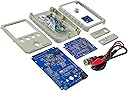
Ottimo oscilloscopio che rispecchia pienamente le caratteristiche indicate: occorre fare attenzione alla manipolazione fatta non delicatamente in quanto il display al momento del montaggio è fissato solo da uan sottile flat cable posta al suo lato sinistro e un suo "sventolamento brusco" comporterebbe a procurare dell lesioni da piegatura alal flatcable con danni irreparabili. Fare attenzione al cablaggio e saldatura del terminale del segnale di prova ( io ho sbagliato il verso e dava impedimento al display a chiudere perfettamente la cover. Il montaggio perfetto è dato che le saldature dei due pin del terminale di prova corrispondano dal lato del display). Altra particolare attenzione bisogna fare al montaggio e saldatura dell'encoder sul suo piccolo Pcb (scheda con circuiti): anche lì ho sbagliato, montando l'encoder dal lato sbagliato con il risultato che non mi funzionavano le varie funzioni dell'oscilloscopio ( non si accedeva al trigger, non si accedeva a mezzo la funzione OK ai valori di misura, si saliva solo di valori sulla scala dei Volt ecc.ecc). Poi mi sono accorto che il corpo dell'encoder andava inserito dalla parte in cui c'è la serigrafia della sua sagoma fisica mentre le saldature dei pin vanno fatte dal lato opposto dove invece si sono i numeri di serie e di versione. Dissaldati sia l'encoder che i pin di assemblaggio dalla scheda pcb dell'encoder; ho risaldato per il verso giusto e finalmente tutto ha funzionato perfettamente. Ribadisco fare particolare attenzione al montaggio e saldatura di questi due componenti indicati sul manuale nel punto 2 di STEP 1 per quanto riguarda il terminale di prova; e nel punto 1 di STEP 3 per quanto riguarda l'encoder, in quanto essendo pcb a doppia pista necessita di una stazione dissaldante ad aria, per dissaldare il tutto , in quanto con pompetta aspira-stagno e saldatore non si riesce a dissaldare perfettamente da ambedue i lati,correndo il rischio di fare danni. Anzi con tutto ciò che ho dovuto usare la stazione dissaldante, ho dovuto utilizzare il flussante e la treccina in rame assorbi-stagno. Quindi occhio alle saldature che poi un reverse diventa molto complicato in pcb come queste a doppia pista. Ripeto gli errori sono stati miei e non del prodotto che se montato per come è dovuto risulta essere di una facilità estrema. Unico neo i due compensatori di taratura posti in un punto scomodo in cui per tararli necessita che la cover dell'oscilloscopio sia completamente disassemblata dal resto; altrimenti non si riesce ad accedere fisicamente con un cacciavite in teflon anti capacitivo. In caso di cambio di sonda, vanno ritoccati C3 e C5 nonostante una sonda professionale da oscilloscopio abbia già di suo il compensatore di taratura.Difatti io ho provato una sonda del mio oscilloscopio Rigol DS1054Z e non è stato sufficiente la regolazione della sola sonda. Avrebbero potuto prevedere due fori sulla cover frontale per facilitare l'accesso al cacciavite(anche se gia nella prima versione del DSO150 i due compensatori erano messi in una posizione ancora più difficoltosa). Comunque una volta tarati i due compensatori C3 e C5, se si utilizza sempre la stessa sonda ad ogni nuova sessione di misura basta semplicemente compensare la sola sonda.Il settaggio di C3 e C5 va eseguito con rispettive tensioni: C3 con sensibilità a 50mV e TSI 0,1 Volt e C5 con sensibilità V a 1 Volt e tensione TSI a 3,3Volt. Il manuale non lo dice ma queste due tensioni TSI (0,1 V e 3,3 V) che compaiono in sovra-impressione sottolineati di blu in basso a sinistra del display ogni qualvolta si preme il tasto AdJ, sono TEST SIGNAL INIECTION cioè Iniezione del Segnale di Test.Il controllo delle tensioni allo STEP 4 a me è corrisposto perfettamente con le condizioni che l'oscilloscopio si acceso per mezz' ora e che la tensione di alimentazione sia esattamente 9,30 volt (io ho utilizzato un Volmetro UNI T UT 61E a 22000 count sul display). Utilizzare sonde con minima attenuazione a 1:10 Ottimo utilizzo con la sonda Hantek T3100 con attenuazione max a 1:100 cosi come già ha attto l'amico Ruggiero che in precedenza lo ha acquistato e consigliatomi su questo venditore. Misurando anche la 230 volt con questa sonda che come ben saprete la tensione di rete Vpp arriva oltre 600 volt.Ho confrontato alcune misure con il Rigol DS1054 Ze devo dive che le forme d'onda sono identiche cosi come le misure rilevate a mezzo funzione OK. testato anche con un generatore di segnale ho notato che con onda sinusoidale a frequenze bassissime (all'ordine di 1-2 Hertz) ritarda nel parametro misure a indicare la frequenza ch e invece già da 10 Hertz è rapida. Viceversa invece da come indicato nelle caratteristiche, riesce a visualizzare la frequenza oltre i 200 Khz ( a me la legge fino a 249 onda sinusoide poi a 250 Khz sballa e non legge più nulla)Perfette anche le onde triangolare e quadra.Per il resto ottimo prodotto al 100%Credo di aver fatto un ottima recensione utile per un perfetto montaggio di un prodotto economico ma validissimo ed eccellente
P**O
Estoy muy contento con este kit.
Se requiere algo de práctica soldando para montarlo, pero no me parece difícil. Yo, que tengo experiencia, lo he podido montar en menos de dos horas. Y ha funcionado correctamente a la primera. Hay que tener una fuente de 9V con cable con conector estándar de 2,1x5,5mm para ponerlo en marcha y ajustarlo, ya que esto no viene en el paquete. También se pude alimentar con otro conector que hay en la placa. En la caja viene un manual en papel en color de 4 páginas que explica bien (en inglés) como se monta y ajusta, y es suficiente para ponerlo en marcha. El manual también indica un enlace a la web del fabricante, donde hay manuales, FAQs, esquemas, firmware, y más cosas. El que traiga una caja completa, también es un punto a favor. Los circuitos impresos están bien hechos y son de calidad. El precio me parece bueno, teniendo en cuenta la calidad del kit, y lo bien que funciona.
C**N
OK
No es muy fácil de montar
Trustpilot
3 weeks ago
1 month ago