🎧 Elevate Your Audio Game!
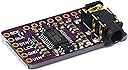
The Teyleten Robot PCM5102 I2S IIS Lossless Digital Audio DAC Decoder Module is a high-quality digital-to-analog converter designed for seamless integration with Raspberry Pi and Arduino. Featuring the PCM5102A DAC, this module delivers superior audio performance compared to onboard analog options, with a pre-soldered stereo jack for effortless setup.
| ASIN | B09C5QX228 |
| Best Sellers Rank | 298,429 in Electronics & Photo ( See Top 100 in Electronics & Photo ) 110 in Digital to Analog Converters 647 in Digital-Analog Converters |
| Brand | Teyleten Robot |
| Customer Reviews | 4.5 out of 5 stars 51 Reviews |
| Interface | USB |
| Interface type | USB |
| Manufacturer | Teyleten Robot |
| Manufacturer Part Number | 3 |
| Maximum Supply Voltage | 5 Volts |
| Maximum supply voltage | 5 Volts |
| Model Number | 3 |
| Mounting Type | Board Mount |
| Mounting type | Board Mount |
| Number of Channels | 2 |
| Number of Items | 3 |
| Number of Pins | 3 |
| Number of channels | 2 |
| Number of pins | 3 |
| UPC | 755454865971 |
J**J
Great Value
Three of them for similar price to one, so was skeptical of quality, but wired it up and worked first try. Definitely would recommend.
S**E
Excellent DAC breakout for embedded audio bring-up
I bought this PCM5102A breakout as part of an STM32H7 embedded audio DSP project, and it ended up being an excellent board for firmware bring-up and real-time audio development. I was using it with independent ADC receive and DAC transmit buses on the STM32, and this module made it very easy to isolate and validate the DAC side of the system during development. Once the I2S framing and clocks were configured correctly, it was stable and reliable at 48 kHz / 24-bit operation. The output quality was more than good enough for real-time DSP testing, latency evaluation, vocal effects development, and general embedded audio experimentation. What I appreciated most is that this board removed uncertainty from the hardware side so I could focus on DSP architecture and firmware behavior instead of chasing analog problems. It is a fantastic low-risk choice for STM32, ESP32, Raspberry Pi, FPGA, or other embedded audio projects where you want to validate your design before committing to expensive custom converter hardware. Documentation varies a bit between sellers, so definitely verify your I2S settings during bring-up, but overall this was a very solid little module and I would absolutely buy it again for future embedded audio work.
C**N
CHECK THE SOLDER JUMPER PADS ON BACK
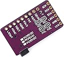
READ THIS BEFORE YOU SOLDER THIS ONTO YOUR PROJECT!!!! I bought this for an MT32-Pi project I was building. The first one didn't produce any sound, so I removed it and soldered another. After talking with some others in the retro computing/maker community near me, they told me the quality is hit or miss. After some time had passed, I was looking at another project that uses these. It noted the BACK side needs to have specific pads soldered/jumpered. I checked mine, NONE of them were set. One quick desolder off the MT32-Pi's PCB, connecting the appropriate pads, and resoldering it back, it NOW WORKS PERFECTLY. Check the attached image and make sure you short/solder these pads as shown so you don't end up like me. When it's jumpered/working properly, there is a red LED on the DAC itself showing it's initialized/active.
H**N
Good sound
Sounds fantastic! Hi-Fi quality from a rasperry pi
C**E
Good value and works for me.
It worked for me with basic sound from a FPGA though I am not an audiophile and can't comment much about the sound quality except that it's good enough for me. Some technical info follows. The is marked as Burr-Brown PCM5102A. The four jumpers 1, 2, 3, 4, at the bottom allows to connect FLT, DEMP, XSMT and FMT, to ground or vdd,. These four signals are also connected to the pads 1, 2, 3, 4, an the default is L, L, H, L. The four digital inputs SCK, BCK, DIN, and LCK, are connected via 220 ohm serial resistors to the IC, and the solder jumper new the SCK pad can be shorted if you don't use SCK (that's what I did, using the IC's PLL). There are two +3.3V LDOs that are fed from the VIN pad. One goes to AVDD and the other goes to CPVDD and DVDD. If you connect VIN to 3.3V they are almost like shorts and pass on the 3.3V. I connected VIN to 5V to have actual regulation and noise filtering on the board. The digital input are still at 0-3.3V level due to the DVDD regulator. The two outputs (on the jack and on the L and R pads) are connected through 470 ohms resistors. I replaced them with 1.5K to reduce the sound level with the headset I use (35 ohms per side). Overall it's a well designed board and I am happy with it.
Trustpilot
3 weeks ago
3 weeks ago