🔋 Boost Your Power Game!
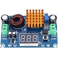
The XL6019 DC to DC Step-up Converter is a high-performance power module designed for adjustable voltage regulation. With a current output of 5A and built-in protection features, it ensures reliability and efficiency for various electronic projects.


S**T
A good step up regulator for 18650 cells.
I've built a home made stack of 18650 cells, every cell individually fused, for hurricane preparedness and needed to step up 3.6 to 4.1 volts up to 5 volts for all the cell phones and other rechargeables in the house.This step up converter has so far tested well for the purpose. (even runs usb fans and lights well)One caveat... Make sure the resistance between source voltage and the converter is very low ohm, and you may want to add an extra electrolytic and mylar capacitor across Vin to keep the converter nice and stable.To thin a wire on input can allow this regulator/converter to get unstable which leads to excess heat/inefficiency. Had this happen. Fixed by jumping to 14~16 gauge and adding aforementioned caps.I'd suggest a home made crowbar circuit to keep any over voltage from accidentally damaging any usb circuits as well.AND DON'T FORGET TO FUSE 9-]In this old techs humble opinion ;~)
J**.
45V is overly optimistic, and it does get hot.
At full load, the modules I received achieve 38V and get very hot. Unfortunately with such a small footprint board, the positive terminals, including the exposed positive pads on the underside, are right next to the ground connected screw terminals leading to very easy short circuit conditions. I found this out when I placed the board on a heat sink and the output wires (to a battery pack) shorted, catching fire lol. That was the battery's fault and that I didn't fuse this connection though so don't blame them for that part. Just remember that these contacts are really close. The module was fine. I like that the components are all nice and beefy, the board is covered in thermal vias to use its ground place as a radiator, and the screw terminals seem very solid. This technique also spreads heat to other components on the board however ;) All traces on the board seem to have more than enough copper for its normal operating range, and the solder joints are very well done. The cleaning and finishing was nicely done as well. The most experienced engineer I work with took a look and also remarked about the build quality. Would be 5 stars if the easy short circuit condition could be resolved. I think the description should mention that additional cooling may be required for operation at full load and 45V is way off from the adjustment range available on the boards I've tested. I will be using these though, and probably will be ordering more. I would use a fuse on the output for safety if you intend to use it with something with also provides current, like in my case with a large battery bank.
C**S
Works perfectly boosting 12v to 24v regulated output
I tested these on the bench. They work as advertised. 5v input to 35v output. I am using for 12v to 24v. I was happy to see the output was regulated, so even if I lowered or raised the input, the output didn't fluctuate. They are rated for 5A. I haven't used under load yet. Will report back if I have any problems.The build quality is excellent. Screw downs are larger than most and strong. Input is one side. Output is the other. The potentiometer adjustment is solid. I've seen really weak ones, but these are tight and move the voltage predictable.These are an excellent buy. I will spray with acrylic/conformal coating to protect the circuit.
M**N
Worst one ever
The most unreliable and poorly designed produce I have purchased from Amazon. I use a lab power supply to test it. Attached on the output end a high precision bench multitester. I suppled input voltage in 1 milli volt increments, from 0 to 3 volts and limited the current to only 0.5 amps to start the test. Long story I noticed extreme output voltage fluctuations that happened randomly. The output voltage swings between 7and 14volts for no apparent reason. No swings in current consumption at all. I also noticed that if I would interrupt the input voltage, the output voltage would change on its own down to 3,4,5,6,7 volts or 14, 8,9,7,4. Etc etc each time I reinstated the input voltage. I played with the little trimmer and I was able to set it up for output of 30volts with no load at all but any fluctuation on the input voltage will change the output by a large margin. Remember a lab power supply with a change of 1 milivots would mess up the outbound plus if I kept the input voltage constant, the output voltage would change each time I disconnected and reconnected the input voltage. It gets better!!! I tested with and without load to the output same voltage swings, I even added an output capacitor and no help. Gets even better, it began to get hot within five minutes, I took thermal images with temperature readings. Remember the voltage swings? Getting hot without load, I did not even bother to hook it up to the oscilloscope, sine this was low cost garbage why spend the time. Even the small capacitors nearby got hot. That is capacitor death in the near future. I imagine the cuircuit was oscillating out of control. I don’t know. Imagine connecting a 6 volt anything to its output only to fry your item when the voltage swings to 14 or 15 volts randomly? And then you turn this thing on, gets even hotter with a small load on and boom! There goes your project. I also connected it to a 3 volt lithium battery and the voltage output was in full swing again. Garbage. See the thermal photos ad look at the temp readings. Those were without a load.
E**L
Wow awesome
Terminals were a great size. It was able to handle the amperage it says. And each come in it's own packaging for future storing and not worry about dust
Trustpilot
1 day ago
1 month ago